Before starting, let's have some basics on Arduino programming and Arduino hardware. I'll be covering both Arduino and ESP32 or 8266 microcontrollers here as ESP microcontrollers are more affordable than Arduino microcontrollers.
Arduino & ESP Programming Basics
Something that you should know
You must have seen that Arduino programming is similar in structure and syntax to C and C++ programming. We write Arduino or microcontroller code in C++ structure.
However, the microcontroller doesn’t receive the C++ code. Our Arduino IDE compiles the code and interprets our code into machine code which is in binary and the microcontroller directly receives and understands the binary code (You will get to know about machine codes in the Computer Architecture Course) then our microcontroller gets programmed.
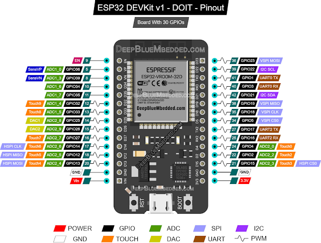
And different microcontrollers have different architectures. The most affordable and powerful microcontroller in our hands is ESP32. This also includes all necessary networking features like Bluetooth Low Energy and Wifi and also a Dual Core CPU capable of dual threading and running two threads simultaneously. The NodeMCU on the other hand the ancestor of ESP32. It does have Wifi but doesn't have Bluetooth and Dual Core.
Programming on ESP32 and ESP8266 might feel slow while uploading the code from the Arduino IDE to the microcontroller board. Arduino IDE is built for Arduino microcontroller boards. This slowdown can be attributed to differences in the architectures and communication protocols of these microcontrollers as ESP32 is not built for Arduino IDE.
And while adding modules, sensors, and other add-ons, always carefully select the voltage. The ESP series microcontrollers support no more than 3.3 volts, the logic voltage of ESP8266 and ESP32 microcontrollers. So all the sensors should have power from 3.3 volts when working with ESP microcontrollers. Otherwise, the microcontroller could get fried or burned.
For Arduino microcontrollers, the logic voltage is 5 volts. The sensors should powered by 5 volts when working with an Arduino microcontroller.
But before starting your project and work, always double-check the maximum and required voltage of your sensors and microcontrollers from Google or trusted online sources.
Let’s get started…
Light Some LEDs
Before starting with our task, some basics…
The most basic code for Arduino or any sort of microcontroller.
If you have an LED, It’s okay; if you don't, just not worry. There is an LED connected to every microcontroller board, you can use that too.
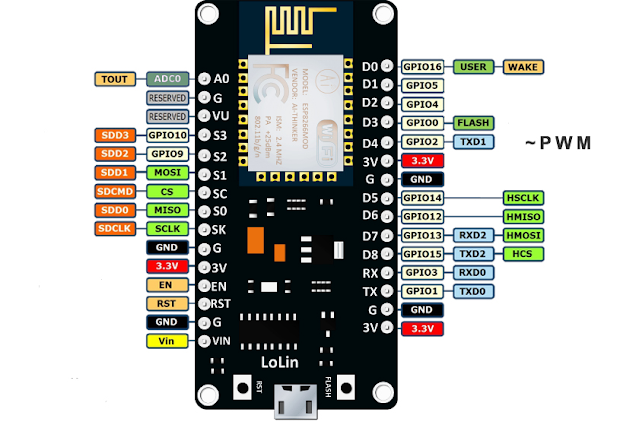
Here is a List of LED pins of common microcontrollers.
*We generally use the number after GPIO in coding. (in this case for the ESP8266 microcontroller, we will use 5)
**This might change, search on Google for the proper pinout for your microcontroller board.
But from lighting some LEDs, what could we learn?
We must use the Arduino digitalWrite function to turn an LED on or off.
Understanding the digitalWrite() function
In Arduino programming, digital pins are used to connect and control external components such as LEDs, motors, sensors, etc. The digitalWrite() function is a powerful tool to manipulate these digital pins.
As we all know, in binary, there could be two states, 0 or 1.
Here 0 represents LOW or Off. And 1 represents HIGH or On.
Suppose, we have an LED connected to the 13-pin of an Arduino.
When the output of pin 13 is 5 volts or above 0 volts, we call it “the pin is HIGH” Alternatively, when pin 13 has no voltages and goes zero, we call it a LOW.
To control an LED's state, we can use the digitalWrite() function to pull up or pull down the output of one digital pin of our microcontroller.
So let’s get to the digitalWrite() function.
The digitalWrite() function has two parameters,
digitalWrite(pin, value)
The pin is referred to as the pin where we want the output. In this case, we are using the blue LED on the ESP8266 board, so the pin will be 2. And to turn on the output (making the output HIGH) we have to give the value HIGH
So, the function will be looking like that,
digitalWrite(2, HIGH)
And for turning the output LOW or turning the LED off,
digitalWrite(2, LOW)
Now let’s get into something practical. We will flash the LED on board.
What You'll Need:
An Arduino board or ESP board (e.g., Arduino Uno, Nano, Mega, NodeMCU, ESP32)
A USB cable to connect your MCU board to your computer
Arduino IDE installed on your computer
Some jumper wires and LEDs (optional for practical demonstration, you can use the onboard LED)
Let's write a simple program to blink an LED connected to pin 2 on the ESP8266 board.
// Define the pin number connected to the LED
const int ledPin = 2;
void setup() {
// Initialize the digital pin as an output
pinMode(ledPin, OUTPUT);
}
void loop() {
// Turn the LED ON
digitalWrite(ledPin, HIGH);
delay(1000); // Wait for 1 second
// Turn the LED OFF
digitalWrite(ledPin, LOW);
delay(1000); // Wait for 1 second
}
Explanation:
We start by defining the pin number (ledPin) connected to the LED as a constant integer. Why constant integer? No reason, but after defining it once in the code, the constant integer couldn’t be changed.
In the setup() function, we initialize the ledPin as an OUTPUT pin using the pinMode() function.
In the loop() function, we use digitalWrite() to turn the LED ON (HIGH) for 1 second, followed by turning it OFF (LOW) for another second, creating the blinking effect.
The delay() function is used to pause the program execution for the specified duration (in milliseconds).
Connect your Arduino board to your computer via a USB cable.
Open the Arduino IDE, copy the provided code, and upload it to your Arduino board.
Watch the LED blink at 1-second intervals!
Understanding the digitalRead() function
And now let’s come to the digitalRead() function. We’ve seen the digitalWrite() function can write to digital pins and manipulate the pin to a high voltage or a low voltage.
With the digitalRead() function, we can read a pin's digital state whether the pin is getting a LOW signal or a HIGH signal. We know that the LOW signal is 0 volts or to GND. And a HIGH signal could be anything greater than 0 volts, it could be 3 volts or 5 volts.
Using digitalRead(), we can get sensor readings, switch press readings etc.
This function has only one parameter. This function returns an output of HIGH or LOW.
Suppose we are reading pin 2,
if(digitalRead(2) == HIGH){
Serial.println("Pin 2 is state is High");
}
Now, let’s get practical. Take an IR sensor, wire your IR sensor to your Arduino or ESP
.
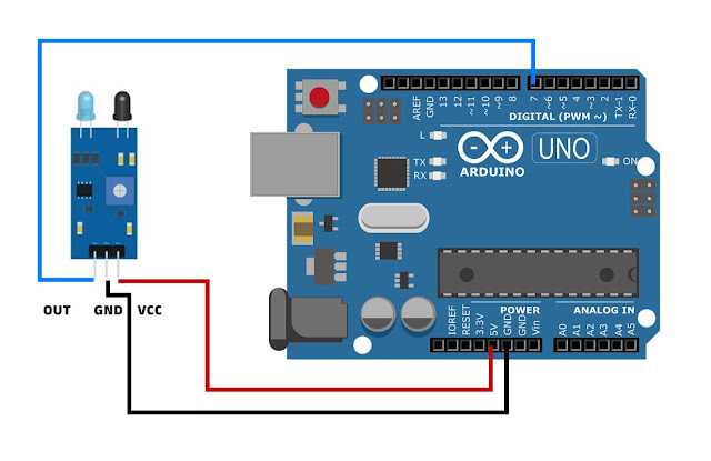 |
| Schematic : For Arduino UNO |
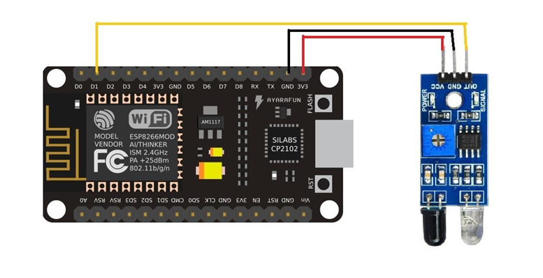 |
| Schematic : For ESP8266 |
Let’s try a code for ESP8266 Node MCU, This will help us take input from IR Sensor and understand digitalRead.
// Code for NodeMCU ESP8266. Sensor Pin Connects to D1 (GPIO 5)
// const int irSensorPin = 7; // Define the pin for the IR sensor connected to pin 7 on Arduino
const int irSensorPin = 5; // Define the pin for the IR sensor connected to D1 on ESP8266
const int serialOutputPin = 9600; // Define the baud rate for serial communication
void setup() {
pinMode(irSensorPin, INPUT); // Set IR sensor pin as input
Serial.begin(serialOutputPin); // Start serial communication
}
void loop() {
// Check if IR sensor pin is HIGH (For Sensors with Active Low state, check if your sensor works.
//If doesn't, change the HIGH to LOW)
if (digitalRead(irSensorPin) == HIGH) {
Serial.println("Sensor Detected Something"); // Send detect message through serial
delay(100); // Optional delay to prevent multiple rapid readings
} else {
Serial.println("Sensor Detected Nothing"); // Send message through serial
delay(100); // Optional delay to prevent multiple rapid readings
}
}
Explanation:
This code establishes communication between an ESP8266 board (or maybe Arduino) and an infrared (IR) sensor. It configures the microcontroller to monitor the state of the IR sensor connected to digital pin 5. When the sensor detects an infrared signal, the Arduino sends a message "Sensor is HIGH" through serial communication. Conversely, if no signal is detected, it allows a brief delay before repeating the process.
If your sensor is detecting something and you are seeing a “Sensor is LOW” message on the serial monitor, then your sensor is active low. That means, when it detects something, it pulls down the output voltage to 0 volts. When the sensor doesn’t detect something, then it pulls up the output to the input voltage. If you face this, then you just have to revert the condition like,
if (digitalRead(irSensorPin) == LOW) {
Serial.println("Sensor Detected Something"); // Send detect message through serial
delay(100); // Optional delay to prevent multiple rapid readings
} else {
Serial.println("Sensor Detected Nothing"); // Send message through serial
delay(100); // Optional delay to prevent multiple rapid readings
}
Tasks
Sub-Task: 1:: Blinking The Onboard LED
Blink the onboard LED four times in two seconds.
Sub-Task: 2:: Blinking The Onboard LED in a Pattern
Create a pattern of flash by yourself. You might have seen airplanes have flashes at nighttime and try to make similar patterns.
Sub-Task: 3:: Making LED Flashing Pattern
In this task, you will need multiple LEDs. Add 4 LEDs to your microcontroller board and then try to create a flashing pattern.
Sub-Task: 4:: Creating a Traffic Light System
Use three LEDs, 1 Red, 1 Green, and 1 Yellow.
Make a traffic light system using three LEDs connected to different pins. Implement the sequence of lights (red, yellow, green) with appropriate delays between transitions. Yellow should flash several times before transitioning to Red or Green.
Sub-Task: 5:: Turn the Light on when you trigger the IR Sensor
Use the IR sensor as a smart switch. Putting your hands over the sensor will trigger the sensor and eventually turn on the LED. After once you trigger the sensor will turn on and stay on. After re-triggering the sensor, the LED will turn off.
Hints: Use flags to store the state of the LED whether it is on or off. Flags are used as global variables to store values across the running program. When IR triggers, change the value of the variable which is being used as a flag. Then in loop(), look out for any changes in the flag variable. If changes, then take any action needed.
ESP8266 NodeMCU v3 Pinout .