
Is your room plain? Big lack of colors? Along with that, are you a content creator or streamer? Does it feel like the saturation accidentally dropped when you make videos or stream? Is the color of your wall as pale as the color of your mind?
What you need is an RGB LED! Just like the RGB LED light I have on the wall behind me right now.
Which I can change the color of or add effects to right from my phone if I want. And once charged, its battery can run continuously for about 12 hours.

And I can charge it using either a micro USB or Type-C, and even run the light while charging it with Type-C. Before this, I bought a lot of gadgets from Daraz during the 499 offer. Among them, I got this LED light strip with a Bluetooth controller for 250 Taka.
 |
| Bluetooth LED Controller |
It uses 5050 LEDs, and very few LEDs are provided, meaning the strip is quite short in length. There is also a Bluetooth controller, which runs on USB power or 5 volts. But its length was so short that I didn't even have the opportunity to practically use it anywhere.
 |
| LED strip bought from Daraz |
 |
| 5050 LED |
To do this, I needed to cut the LED strip into small pieces. There are marks in the middle of the LED strip indicating where to cut.
 |
| Where to cut the LED strip |
I will cut this strip right there. Now, I'll attach these strips onto a foam board one after another.
 |
| Need to attach it to the board using the double-sided tape on the back of the strip |
There is glue on the back of this strip, so it can be attached using that. After finishing attaching them, I will apply solder to all the solder pads.
 |
| Will tin all the solder pads by applying solder |
Then I will connect the separately cut LED strips in parallel. Initially, I made the connections like this. I extracted wires from an old Ethernet cable and used them for the connection.
 |
| I will connect the separately cut LED strips in parallel |
Then I noticed that I couldn't attach the next ones like this because I didn't place the LED strips properly. Moreover, it was taking a lot of time. So I had to find a new way. I had some enamel-coated wire from a solenoid lying around, which everyone knows as coil wire. I soldered all the LED strips using those.
 |
| The condition of the board after soldering in a parallel connection |
 |
| Enamel coated wire |
Soldering in two different ways makes the whole thing look quite messy, but as long as it works, it's fine for me, so I didn't sweat it. Now I'll check a bit to see if all the solder joints are okay and if there are any loose connections; if there are, I will fix them by soldering.
 |
| Soldering in two different ways makes the whole thing look quite messy |
It was Ramadan time, so I left it at that for today and moved on to the next day.
Now I will work on its box and the associated electronics.
Now, before starting the rest of the work on the box, let's get a bit familiar with the remaining electronics. So that we can understand exactly where and how much of the board we need to cut or drill.
The electronics that we might need to keep inside the box are the Bluetooth controller for our light, and a battery, which I stole from Rafi's old power bank.
 |
| Components that might need to be used |
Electronic components that might be needed...
- Type - C TP4056 Battery Charger Module
- 3.7v Lithium Ion / Lithium Polymar Battery
- 5 LEDs of different colors (4 for battery levels, 1 to indicate power on/off)
- An IRF3205 mosfet (n-channel mosfet)
- A 100k ohm resistor
- A PC817 optocoupler
- Veroboard so you can solder
- Push Button
And a power bank module which I myself won't use a bit later because it got ruined. Many might be wondering why there isn't a big power switch, I'll explain that shortly.
 |
| Power bank module with battery level (This is the one that got ruined first :p) |
We will primarily use the LEDs as a battery level indicator. Which we get in the power bank. For that, we'll make an LED board using a veroboard.
And a little later I discovered that these yellow LEDs draw a lot of current, which our power bank module can't even provide. And this power bank module is also ruined.
 |
| These are the culprit yellow LEDs, which consume a lot of current |
So again, I replaced all the yellow LEDs with completely white LEDs. And I found a new power bank module that has a battery level indicator.
 |
| Attached the white colored LEDs |
The power bank module I found has a switch. Pressing this switch shows the battery level. So, to get access to this switch from the outside of the box, I will attach a large switch in parallel with the power bank's switch. To easily attach it to the box, I will solder the large switch onto a board.
 |
| To easily attach it to the box, I will solder the large switch onto a board |
And if you press and hold this switch, a small LED lights up as a torch on the power bank board. When this LED lit up by pressing and holding it, I thought that this could be used as the switch for the entire LED strip. Pressing and holding it will turn the strip on, and holding it again will turn it off. Wouldn't that be nice?

Now, making a direct connection to the LED strip won't work, so here I will use a MOSFET so that from the current of the small LED, we can switch a MOSFET to turn on the high-current LED strip.
 |
| MOSFET |
So how does a MOSFET work?
You'll get bored if I talk too technically about MOSFETs. In short, a MOSFET is a type of transistor, and a transistor is a kind of switch that is used in various electronic circuits; even our computer CPUs have hundreds of billions of transistors.
And there are two types of MOSFETs, P-channel and N-channel. We will work with the N-channel. A lot of DC current can pass through a MOSFET. 20-30 amps is an understatement. There are various types of MOSFETs in the market based on categories. We will use an N-channel MOSFET.
A MOSFET has 3 pins. Gate, Drain, and Source. The gate pin is used to control the conductivity between the drain and the source. Meaning, how much you will open or close it.

If you apply a positive voltage to the gate pin of an N-channel MOSFET, it will open the MOSFET, meaning it opens the gate, no matter how small that voltage is. And even if you then turn off the voltage to the gate, this gate remains open. The reason is that the charge you applied to the gate doesn't actually reach the MOSFET's drain. This charge itself keeps the MOSFET's gate open. And keeping the gate open means current will continue to flow through the source and drain of the MOSFET. This is the characteristic of a MOSFET.

Its efficiency is very good. But as soon as you connect the gate pin to ground or a negative pin, the charge will go to ground, and the gate will close.
To trigger the switch in this N-channel MOSFET, we will use an optocoupler. An optocoupler is pretty much a light and another light sensor inside a tiny IC.
 |
| PC817 Optocoupler |
In an optocoupler, the two sides are completely separate, much like a relay switch; you can switch from one side to the other. But here the switching happens via an LED or light. We can't see this because it happens inside this IC. By using an optocoupler, the MOSFET's circuit and the circuit inside our power bank will remain separate, preventing random voltages from crossing over and ruining anything.
 |
| The optocoupler works somewhat like this |
Now, if the optocoupler triggers the MOSFET once, and after that if the gate just stays on, then there's no point!
So we will attach a relatively large value resistor, which I've set to 100k, to the gate pin along with the ground.
 |
| MOSFET switch circuit |
 |
| This is called a pulldown resistor |
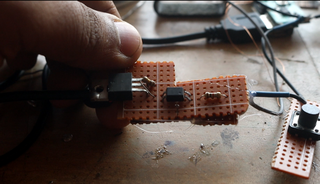 |
| I'll solder and attach the switch circuit onto a veroboard |
Anyway, since testing the MOSFET is done, I'll solder and attach the MOSFET switch circuit onto a veroboard.
Now I will set the electronics inside the box using hot glue. First, I'll place the battery. Then, while placing the other components, I noticed that keeping the jack plugged into the power bank module's USB port was wasting too much space. So I ditched the USB jack and soldered the wires directly.
 |
| I ditched the USB jack and soldered the wires directly |
Now I will start drilling, first for the LED lights. To drill properly, you can rub a little pencil graphite powder on the heads of the LED lights and use that to mark where to drill, that way the measurements will be accurate. Alternatively, you can place the LEDs directly on the side board instead of soldering them to a veroboard like me. Now I'll install the push switch. For this, I'll take measurements using another push switch of the same size and drill a hole. Then I'll set the switch in place.
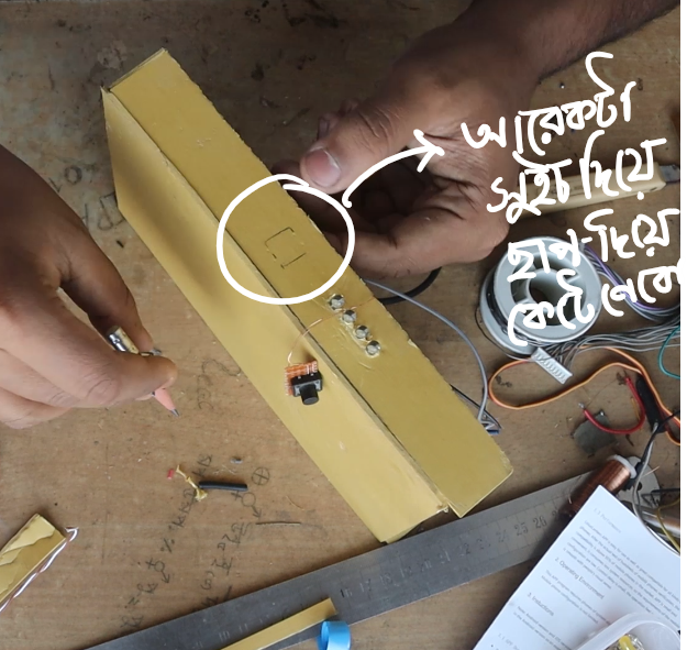 |
| I will take measurements using another push switch of the same size and drill a hole |
Now I'll set up the power bank module, then extend the power bank module's micro USB port towards the outside. Along with that, I will attach another LED in parallel with the power bank's torch LED, so that when the LED strip turns on after pressing and holding the button, an LED indicator will also be visible.

I forgot to add a resistor with the indicator LED. Because the white LED that was here before as a torch required a slightly higher voltage. Now, the orange LED I am using needs a slightly lower voltage, otherwise the LED will heat up. So I installed a current limiting resistor equivalent to 220 ohms.
It might seem like our project's work is finished.
But there is still a problem with it.
Power bank modules are made to charge phones. When we try to light the LED at low brightness, the LED will draw less current. Seeing the low current, the module thinks that the mobile phone being charged is fully charged, which is why it's drawing less current. Because of this, it auto-cuts and shuts off the output, and the power bank goes into sleep mode so the battery holds its charge for a long time. Usually, if the current drops to within 50 or 100 milliamps, the power bank turns off like this. This can be fixed, or you can choose not to if you don't need low current.
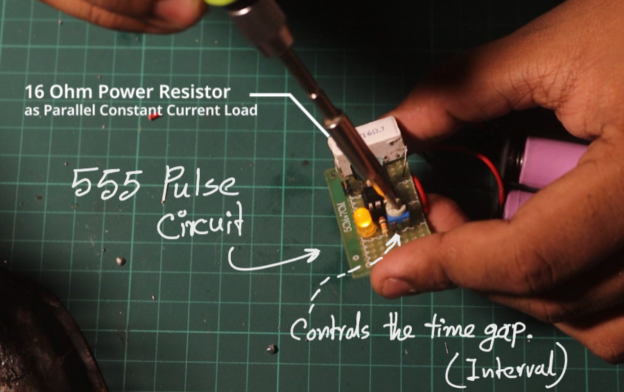
The solution is, we have to measure and figure out exactly how often the power bank auto-cuts on low current. Let's assume that after receiving low current, the power bank shuts down within 10 seconds; then we have to build a timer switch that activates right before 10 seconds, say every 8 seconds, and provides a load of more than 100 milliamps to keep the power bank module awake, meaning it won't let it sleep.
So for this, I will use a 555 timer IC to send power to a resistor for exactly 1 second every 8 seconds. Doing this will prevent our power bank from turning off.

- NE555 Timer IC
- 1 Mega Ohm Potentiometer
- 10k Ohm Resistor
- BC557 Transistor
- 1k Resistor
- LED Red
- 22uF Capacitor
- 100 Ohm/ 40 Ohm / 10 Ohm Power Resistor
- Veroboard

And when we are not using our light, if we want to be able to use this light's battery for other purposes, we'll extend a DC socket so that its battery can be used from the outside.

So finally, a practical use was found for that small, short-length 5550 RGB LED strip. By combining a regular LED strip, an old power bank battery, a Bluetooth controller, and some electronic components, I built my very own portable RGB video light. From room background lighting to making videos or streaming, it will come in quite handy in both areas.
It's not like everything in this project went perfectly the very first time. In fact, while working, I had to redo things a few times. Sometimes I used wires from an Ethernet cable, sometimes I soldered with a solenoid's enamel-coated wire. A power bank module got ruined, LEDs had to be changed, and to prevent the power bank from shutting off on its own at low brightness, a pulse circuit using a 555 timer had to be added. These hassles are actually what made the project more interesting.
In the end, instead of restricting the battery just for this light, I also left a DC socket for external access. As a result, if needed later, this battery can be used in some other project as well.
To me, the most fun part of this project is that what started off as a small and somewhat useless LED strip was turned into a highly useful gadget with just a bit of thinking, some soldering, and by utilizing old stuff lying around.
That's the fun of DIY projects. It's not necessary that you'll always need new and expensive components. Often, the materials for your next project are hidden right within the old electronics lying around at home.
However, you definitely have to be careful when working with lithium batteries and high-current LEDs. A short circuit or improper charging can ruin both the battery and the circuit, and can even pose a safety hazard.
All in all, starting from a small LED strip, I ultimately built a rechargeable, Bluetooth-controlled portable RGB light.
Today's project ends here. I'll see you again with a new project ahead. Until then, instead of throwing away old electronics, think for a moment about what else can be built with them.